Guidelines
Laser Cutting Design Guidelines
Laser Cutting Guidelines
Using the Correct File Format
Files accepted by my system:
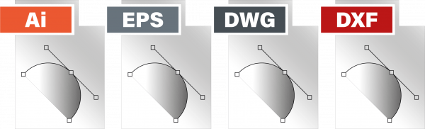
Laser cutting needs vector cut paths. For an instant laser cutting quote, upload your DXF (preferred) or DWG part drawing and select the material, thickness and quantity in the quoting tool.
AI and EPS artwork files can be sent directly to Shug for review and conversion assistance. They are not upload formats for the instant quoting tool. Contact Shug if you need help preparing a file.
- AI (Adobe Illustrator)
- EPS
- DWG
- DXF (Preferred)
If you design your parts in Adobe Illustrator, please send me the original – native – Ai file.
I will do the conversion from my side. Please save in CS5 or lower.
Should you only have a raster file such as a JPEG, GIF and PNG etcetera available, you are welcome to contact me for a customised quotation on file conversion to a vector format.
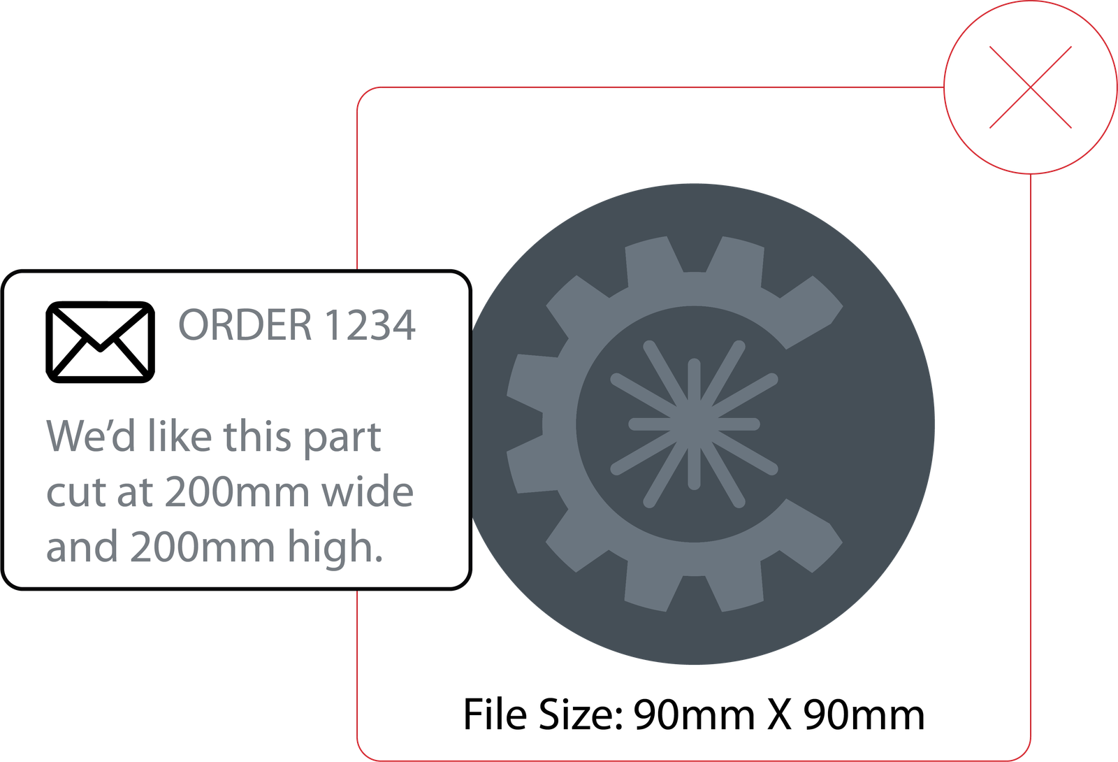
Scaling of Artwork Must be Correct
Artwork must be scaled to the exact size you require it cut – 1:1 scale.
No design will be adjusted, based on the written dimensions on the drawing.
My system cannot recognise these instructions and they will be ignored.
Please don’t do this:
I prefer to work in Metric Units (mm) when possible, but imperial inches units are also acceptable.
Please Note: No other measurement formats such as feet, meters, yard etc. can be accepted.
If your raster file has been converted to a vector file, please ensure that dimensions are verified.
Printing your design at 100% scale, may help you confirm dimensions and scaling.
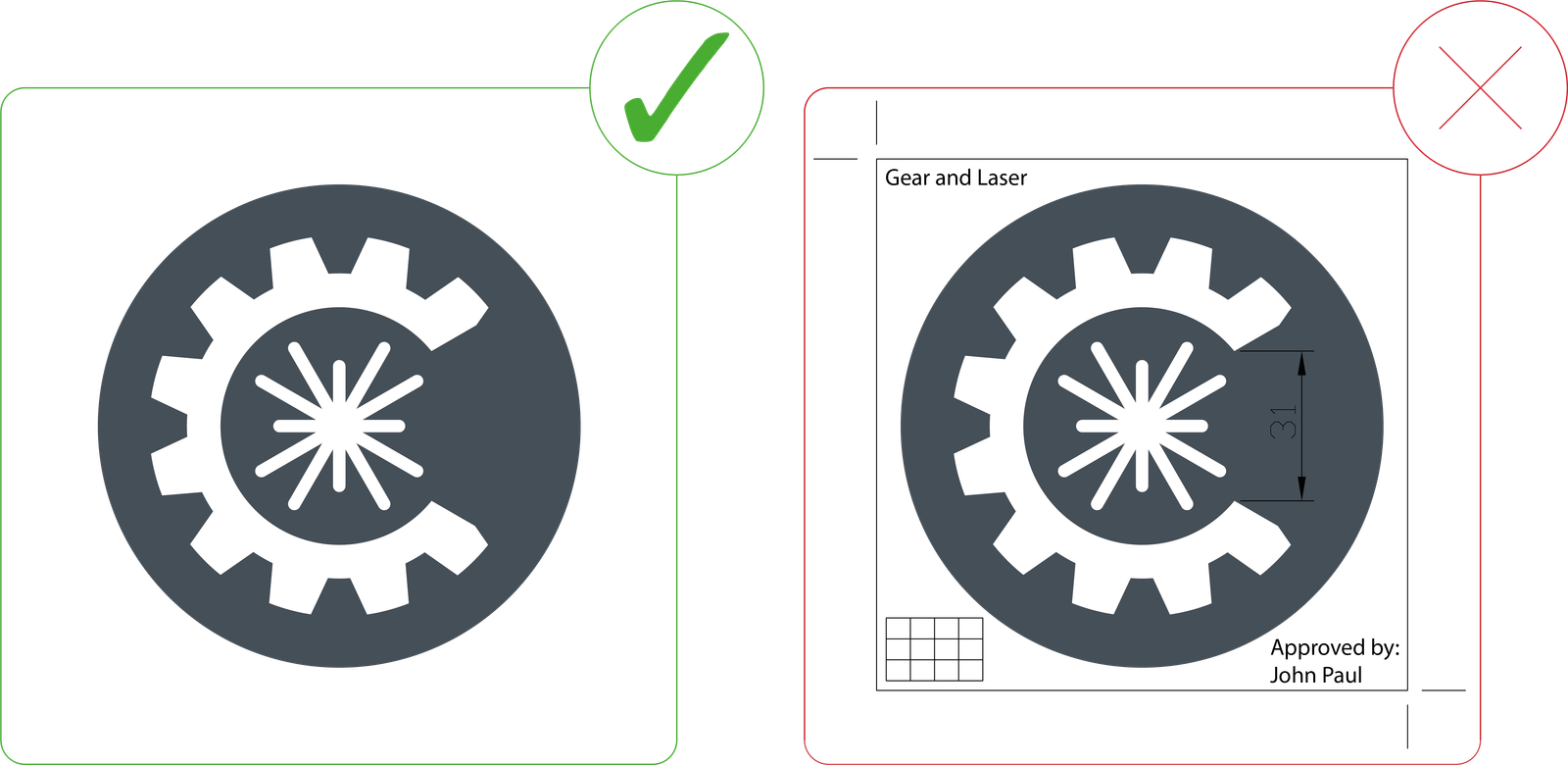
Files should only contain your parts/cut-paths
Ensure that all instructions, dimensions, notes, borders and unused objects are removed from your file, leaving only the actual cut-path that the laser must follow for cutting.
Any additional instructions, such as quantities, can be written on the order.
Should I have any additional queries, I will contact you immediately.
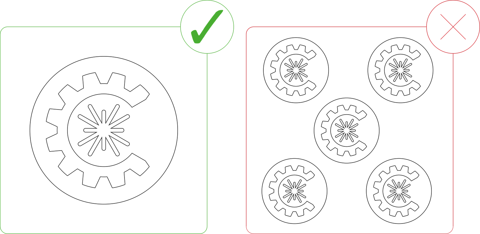
Files should not contain multiples of one part
Shug arranges the parts on the cutting sheet (nesting) to use the material efficiently. Supply one part per drawing rather than pre-nesting repeated copies.
For an instant quote, upload the part drawing and set the required quantity in the online quoting tool. Check the material, thickness, dimensions and quantity before proceeding.
For a direct enquiry, include these details with your files: Part 1 — 3 mm hot rolled mild steel — quantity 30, for example. You can also use the fillable laser cutting quote form (PDF) and contact Shug for drawing assistance or additional project requirements.
Convert All Text to Outlines
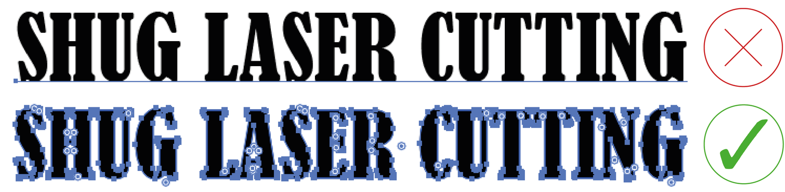
CNC laser cutters are unable to process cuts properly if there are any ‘active’ text boxes in a vector design.
When including text in your cut, simply convert ‘active’ text boxes into shapes or outlines. This can easily be applied in most design software programs.
Checking whether there are any ‘active’ text boxes, can be done by hovering a cursor over the text.
Should it show that the text box is editable as text, it will need conversion into a shape.
In Illustrator, this is called “converting to outlines” and in some CAD software, it might be called “explode” or “expand.”
When in doubt, contact your software provider or search the internet for tutorials.
Shapes and Text Should Be Connected with Bridges
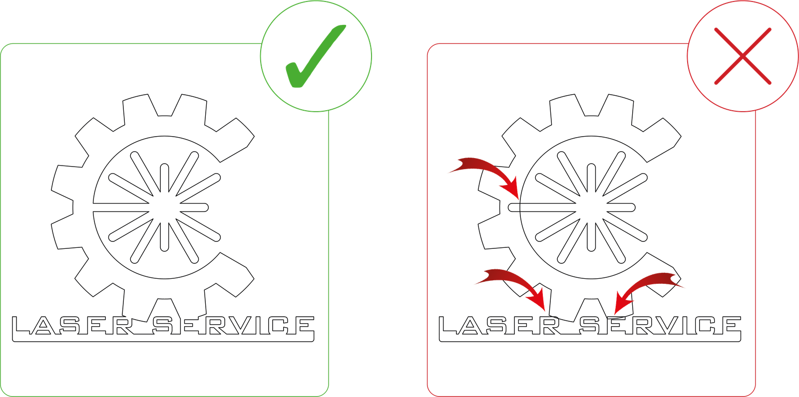
Please note the example below.
On the right, the shapes marked in red will be discarded, as they are not connected to the outer shape. Should this be an intended part of the design, it will bear no influence.
If not, installation can be hindered with the usage of extensive text in the design, or when a sign is being designed.
This can be corrected by creating ‘bridges’, as par the example below.
Think of your design as a stencil, as this will reduce the number of ‘loose’ pieces that will have to be brought into consideration during installation.
Should you require many, small parts, please note this on your order and your request will be fulfilled.
Noting that we want our clients to have sufficient knowledge of the installation or mounting process.

Shapes, Holes or Cut-outs to be at Least 50% of the Material Thickness
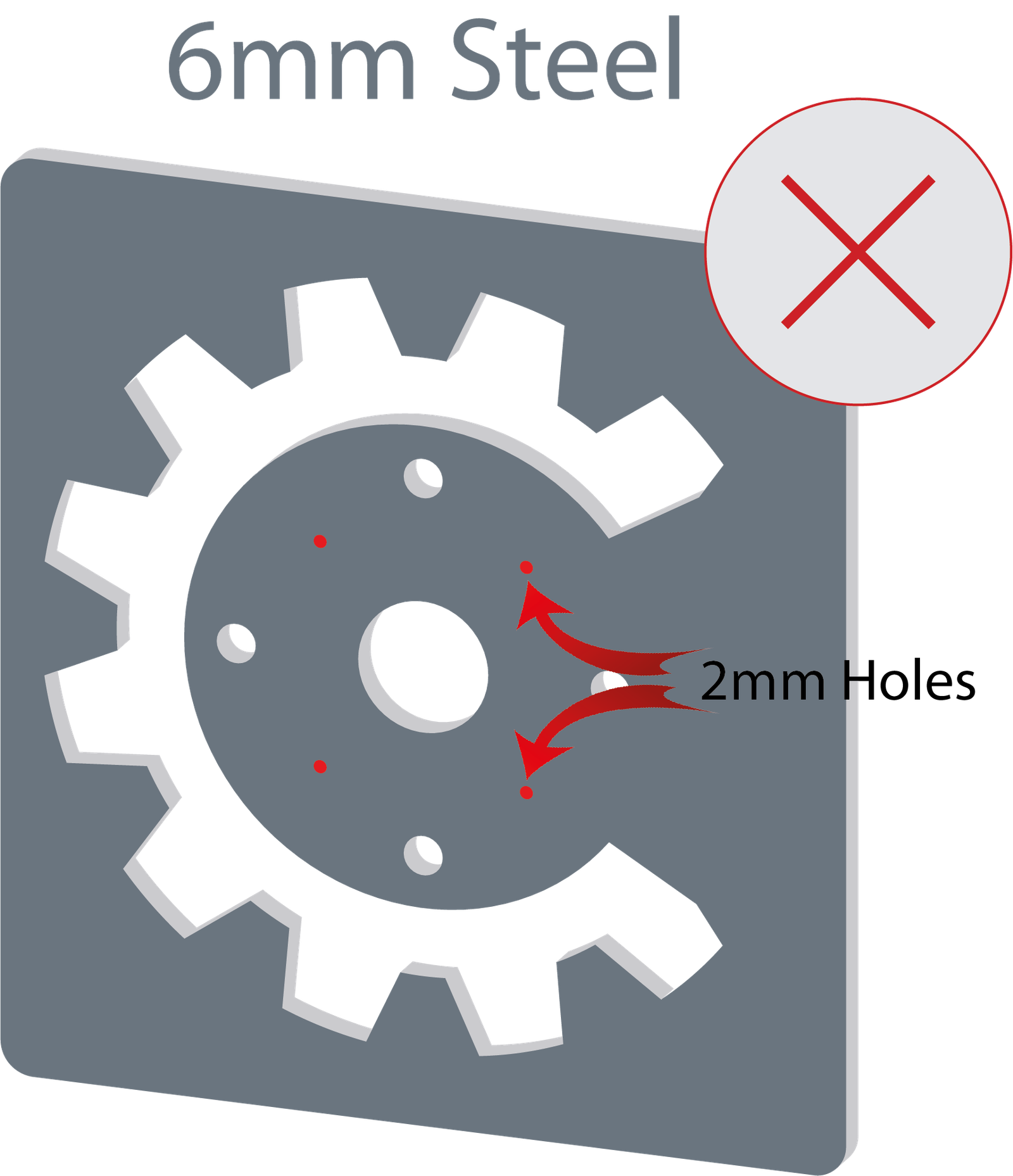
The laser is unlikely to cut holes or internal shapes or patterns accurately, that are smaller than 50% of the material.
When the laser begins cutting, it ‘pierces’ the material, requiring a certain diameter allowance for the holes or internal shapes or patterns.
Should your material be 6mm thick, the smallest accurate hole, expected to be cut would be 3mm in diameter.
As a general rule, calculations should be kept to greater than ½ material thickness.
Following the example below, it can be seen that the red circles, would be too small to cut correctly.
Avoid intersecting or common lines
Keep separate parts apart and remove any overlapping or duplicate cut lines.
No lines should overlap or intersect with each other as the laser cutter cannot interpret these lines correctly and will not cut these parts.
These issues can be spotted easily by viewing your design in Wireframe Mode or in Outline Mode – Illustrator, in the design software.
Your file should not contain empty objects or contours
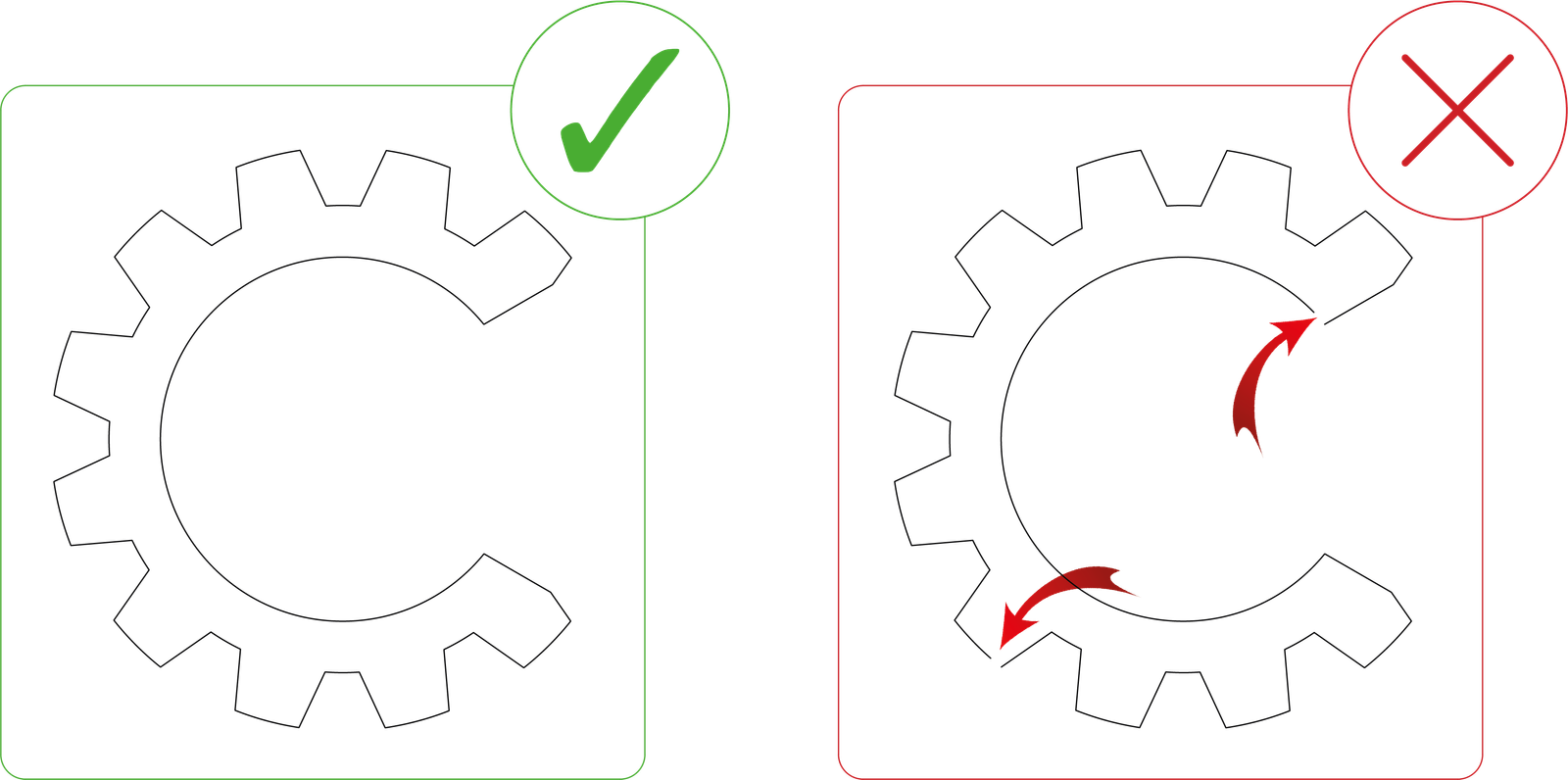
The definition of ‘Open contours’ is when your shape is not connected all around the perimeter.
Remembering that the laser follows the cut-path of your shape, if your shape stops, the laser is unable to continue.
A quick method of finding these issues in your design is to view your design in Wireframe mode or Outline mode in the design software.
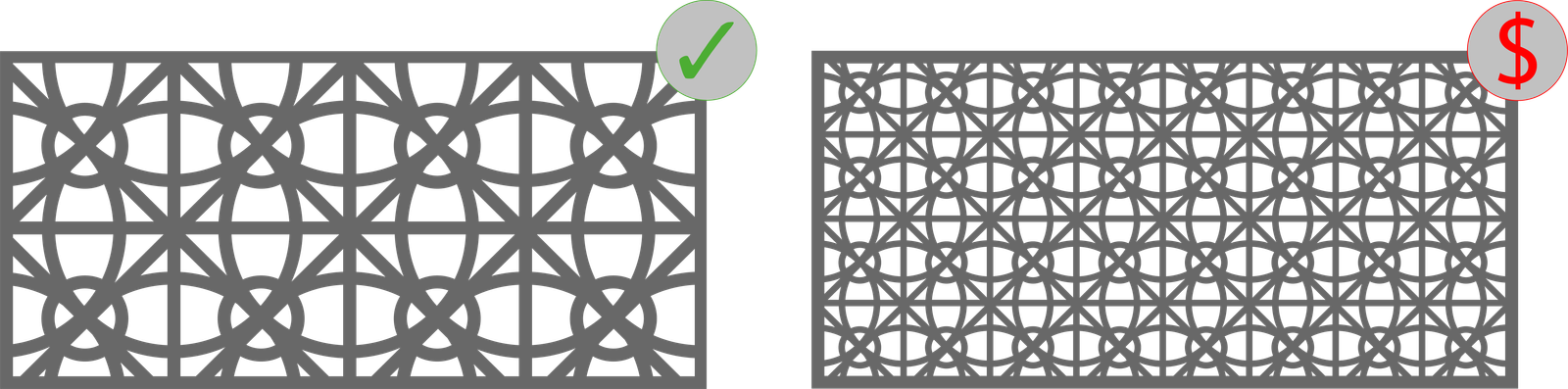
Minimising the Complexity of a Design
Manufacturing costs increase with each laser piercing and cut that is required.
With intricate designs, there are often multiple smaller pieces or delicate details in the design, which can result in a less sturdy finished product, more inclined to breakages.
Simplifying a design will ensure that costs are kept to a minimum and the finished product is more stable.
Following a few basic suggestions during the design process, can result in finished products of impressive art, equipment and prototypes.